Motorising a mount
One of the common upgrades done to mounts with manual controls is a motor upgrade. Out of the box some cheap mounts don't come with any, so slewing to the desired target and tracking it all needs to be done manually. Sometimes there is an official motor kit available, but it is rather expensive for just adding basic slewing and tracking. That is why the community has stepped in and modelled mounts to add stepper motors to this mount, created software to automatically control the motors and add GO-TO functionality.
Adding Motors
The first step in motorising a mount is adding the motors itself. The most common type of motor used in this type of upgrade is a NEMA 17 stepper motor. These types of motors have standardised dimensions and allow a controller to have the motor make precise changes in position. That is also how they differ from normal DC motors that don't allow you to change the position in a precise manner.
There are three ways to mechanically connect the motor to the driveshaft of the mount: direction connection, belt drive and gear drive. Direct connection and belt drive are the recommended methods due to them having no or almost no backlash. The advantage of the belt drive is that you can add extra gearing to your mount. If you use for example a 20 teeth pulley on the motor and a 60 tetth pulley on the mount driveshaft, you can add an extra 1:3 reduction. If the extra reduction isn't needed and it is easier to mount the motor in line with the mount driveshaft, then a direct connection can be used.
There are motor kits available for some mounts. They may be an easy option if you don't have (access) to a 3D printer or you just want to buy something off the shelve. These kits can also be bought together with preconfigured OnStep controllers, making it a full plug-and-play experience.
3D printed motor mounts
EQ3-2 (CG-4) NEMA 17 Mounting Brackets
Saiti on thingiverse made excellent mounting brackets for NEMA 17 motors for the EQ3-2. Downside is that they use some harder to get GT2 belts.
Bill of materials:
- 2x NEMA 17 motors (use 0.9 degree / 400 step models with high torque)
- 8x M3x12 bolts
- 8x M3 washers
- 2x M5x16 bolts
- 1x M5 nut
- 3x M5 washers
- 2x GT2 48 teeth pulley wheel
- 2x GT2 16 teeth pulley wheel
- closed loop 172 mm belt
- closed loop 136 mm belt
Can be printed with any printer that fits these parts, keep infill high so that bolts can be tight. 60% as mentioned on the thingiverse page might not be enough. Print the parts in the following orientation to add strength where the M5 bolts go.
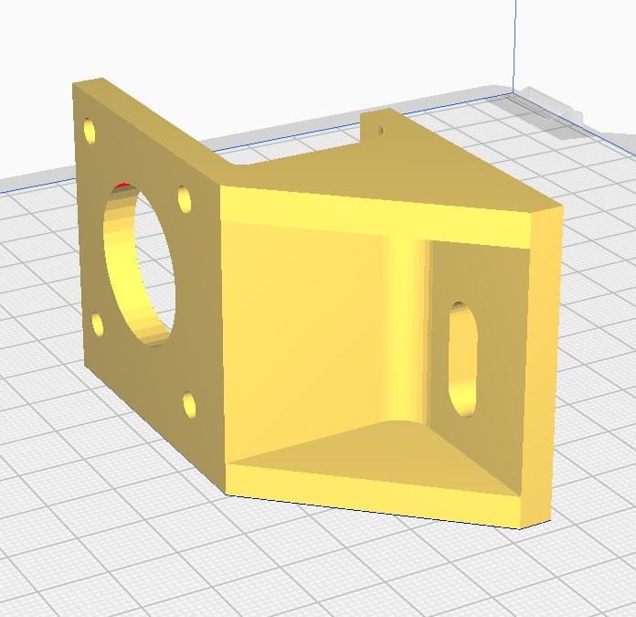
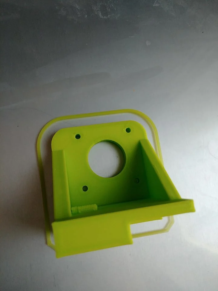
Do note: this model does not come with any mounting points for connectors. You might have to model some mounting brackets for those and glue them on, there should be enough space for that on these motor brackets.
Backup of models: DE_v4_176_rounded.STL RA_EQ3-2.STL
OnStep Mount Controller
By far the most common way of making a controller to motorise a mount is by using OnStep. This is an open-source software project aimed at creating an easy to use way of controlling a mount with a phone, computer or handheld controller.
Just like with the motor mounts, there are OnStep kits available. For some mounts they can be bought preconfigured, making it a plug-and-play experience.
Existing OnStep controllers
(only ones supported by OnStepX listed, because ones that are not are basically decrepit at this point)
- STM32 Bluepill
- Big Tree Tech SKR PRO V1.2
- MiniPCB V1, V2
- MaxSTM V3
- MaxPCB V1, V2, V4
- MaxESP V2, V3, V4
- JTW Manticore
- Fysetc S6
- Fysetc E4
- CNC V3
Older versions are not guaranteed to work, so always build the most recent version.
Core components of an OnStep controller
There are a number of OnStep controller designs out there, see which one has the features you need. Usually the documentation of the controller explains how the different components are connected.
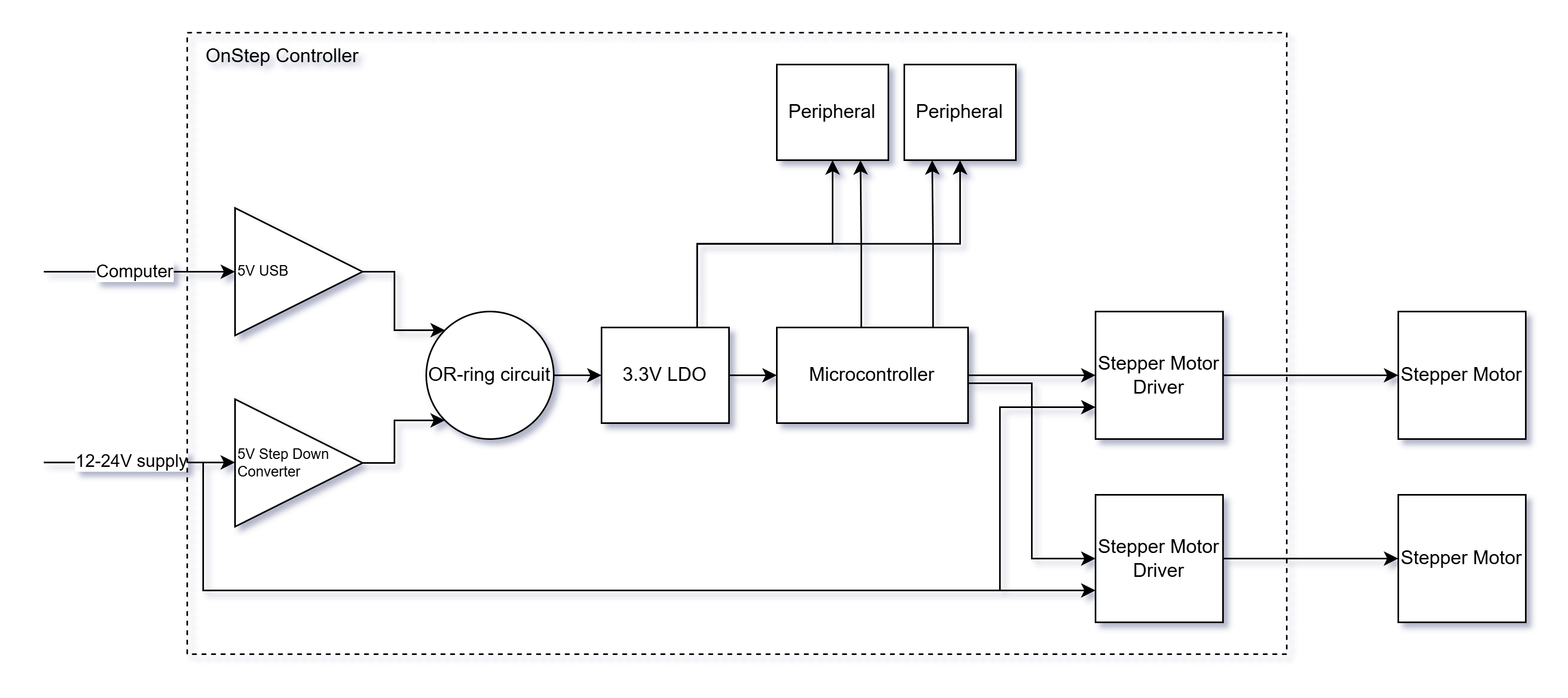
Microcontroller
This little chip is the brains of the operation. It does all the calculations, logic and communication. These chips are common in large and small devices and are a cheap way to add loads of functionality on the fly to any sort of device. The microcontroller is what actually runs the OnStep software.
The most common microcontrollers used to run OnStep are:
- The ESP32 series of microcontrollers from Espressif are ideal to run OnStep on because they are cheap, fast, easy to get and easy to program.
- The STM32 is another 32-bit microcontroller, but the ones supported by OnStep aren't as fast as the ESP32, are harder to program and generally speaking offer less features.
- Teensy microcontrollers are extremely fast microcontroller boards that muddy the water between microcontrollers and full-on CPUs used in tiny computers. They are a lot more expensive than the STM32 and ESP32.
When using OnStepX on the ESP32 you can use the WiFi/Bluetooth radio of the ESP32 itself, removing the need for an external WiFi/Bluetooth module.
There are a lot of ESP32 variants. Newer ones like the C3, C6, S2 and S3 may seem attractive because they have built-in USB support, but sadly there are issues with the OnStep ASCOM and INDI driver that make these microcontrollers incompatible. WiFi control still works fine, only USB communication doesn't work.
For most applications the ESP32 is the best option.
Stepper motor driver
Stepper motors cannot be connected directly to the microcontroller. The voltage and current is too high for the microcontroller to handle. That is why stepper motor driver boards or chips are used. These drivers can deliver high current (>1A) at higher voltages such as 12V or 24V and offer special features like microstepping that lets you increase the resolution of a motor.
These drivers have a number of connections:
- Vmotor: Supply voltage for the motor. Commonly between 12V and 24V.
- Vio: Reference voltage from the microcontroller, so that the driver knows what the logic LOW and HIGH voltages are. Commonly 3.3V or 5V.
- GND: 0V or GND is a common rail across all devices in your setup.
- STEP: If this input changes state (LOW->HIGH or HIGH->LOW) the driver makes the motor do one step.
- DIR: The state of this pin decides the direction of the step.
- Enable (EN): This is a type of pin found on a lot of chips. The datasheet tells you what level this pin needs to be at to put the device in an active state. Some driver boards already put this pin at the level needed for active state.
- Serial input: Some drivers have a serial input and usually these are optional. They offload some of the tasks from the microcontroller. For example the serial interface can be used to make the driver rotate the motor at a set speed.
Stepper motors can create extremely fast changes in the current. Long wires from the power supply to the stepper motor driver might make the voltage dip, causing issues. Put a large electrolytic capacitor (100 uF - 470 uF per driver) close to the driver. The voltage rating must be at least 50% above the expected supply voltage.
WiFi/Bluetooth module (optional)
If you want to have WiFi or Bluetooth functionality then you would add a module for this. The ESP8266 is the most common option for this. If you are using an ESP32 as your microcontroller then you can also use the new OnStepX which can make use of the WiFi/Bluetooth radio on the microcontroller itself. So no need for an extra module.
Real Time Clock (optional)
The RTC is used to keep track of time, and in some cases location and other settings. There are two options here, an RTC module or a GPS. If you are ok with setting the time and location every time you start the controller then this can be left out. Applications such as NINA also write the time and location automatically to the device, making an RTC a bit unneeded.
Step Down Converter (optional)
If you want to power the microcontroller from the same power supply as is used for the motors, you will need a step down converter. Usually the output voltage is set to 5V. LDO voltage regulators aren't recommended because they will have to dissipate a lot of power when the input voltage goes above around 9V. This module can be omitted if the microcontroller will always be powered from USB and never has to work on it's own from the main power supply.
Other peripherals (optional)
Enviromental sensors such as a BME280 can be added if needed, but for most basic builds these can be left out. A reticle LED in the polar finder could also be controlled by OnStep. For more information about the settings for devices, see: https://onstep.groups.io/g/main/wiki/30067